Creating a Printed Circuit Board to control fans in Klipper

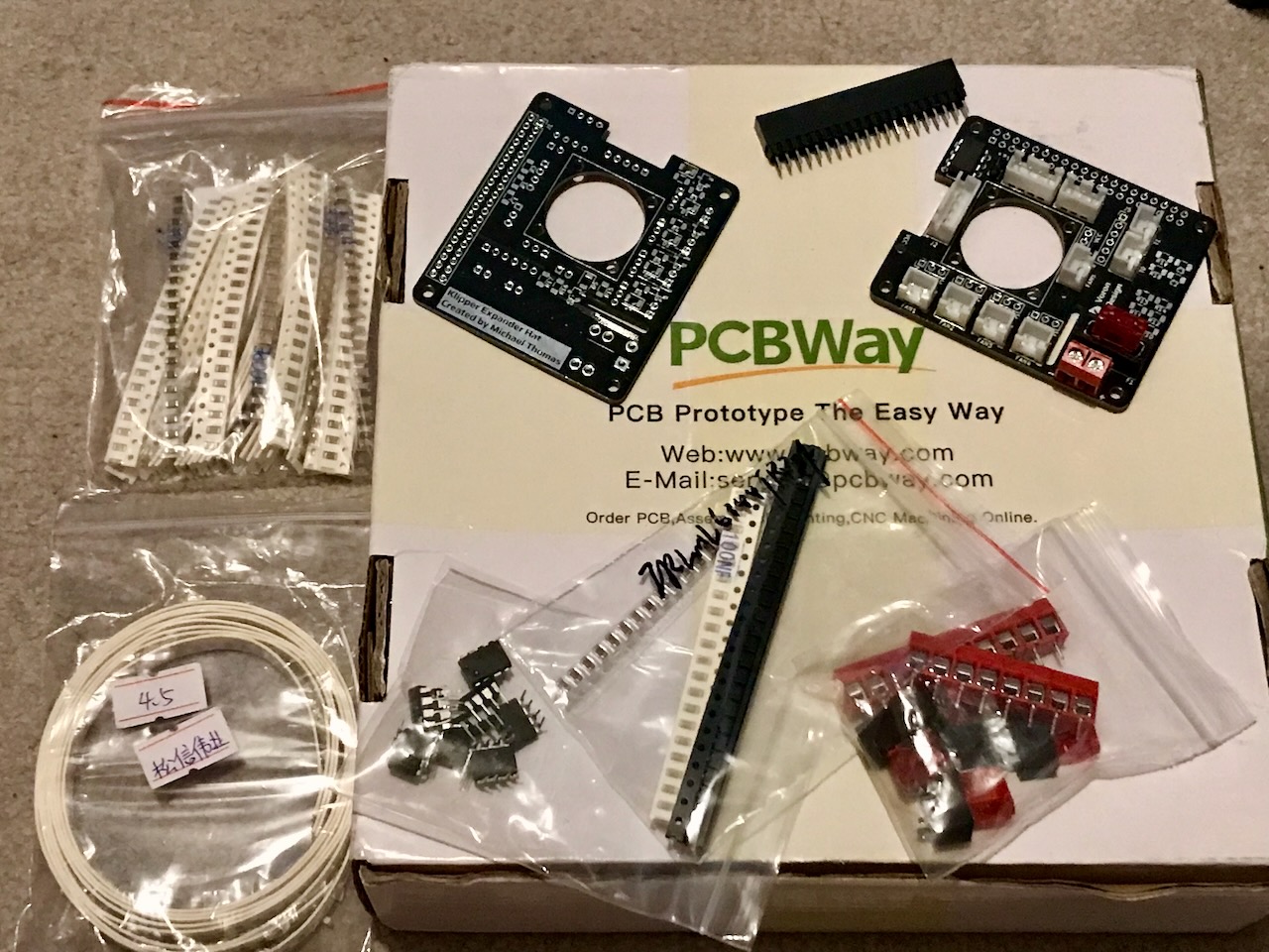
Table of contents
- What is the Klipper Fan Hat?
- What about the Klipper Expander?
- Printed Circuit Board
- Parts Required
- Assembly and Testing
- Flash Hat EEPROM
- Klipper Setup
What is the Klipper Fan Hat?
I wanted to explore making a Raspberry Pi Hat based on Tim Abraham's Klipper Expander to control additional fans using the Raspberry Pi as a Secondary MCU in Klipper Firmware.
What about the Klipper Expander?
The Klipper Expander is designed to add 4 additional Mosfet outputs, 2 thermistor inputs, a Neopixel output, a GPIO Header and an I2C header that can be added as a secondary Klipper MCU. The Klipper Fan Hat is supposed to be a re-imagining of this, which can be attached on top of the Raspberry Pi that is used as the Klipper Host.
The Klipper Fan Hat is not supposed to be a replacement for the Klipper Expander, the Klipper expander can handle more current as it has wider PCB tracks than this PCB. Therefore the Klipper Fan Hat should only be used for lower current devices such as fans. Also, the Klipper Fan Hat does not support Neopixels due to space constraints of fitting it within the footprint of a Raspberry Pi Hat.
Klipper Fan Hat features:
- SKR Pico compatible input for powering the Pi and Serial communication
- 5 Mosfet outputs (with 2 pin JST-XH connectors standard on most fans used on 3D printers)
- Voltage selector jumpers to power each fan from either 5V or VCC supplied by screw terminal
- I2C and 1-Wire and SPI headers for connecting accesories to the Raspberry Pi
2 thermistor inputs(removed, see Testing Section to find out why)- 2 headers connected to General Purpose GPIO pins for accesories such as Filament Run Out Sensors
Printed Circuit Board
The PCB (printed circuit board) was designed in KiCad 7 and I have created a repository on my GitHub with the design files and Gerber files.
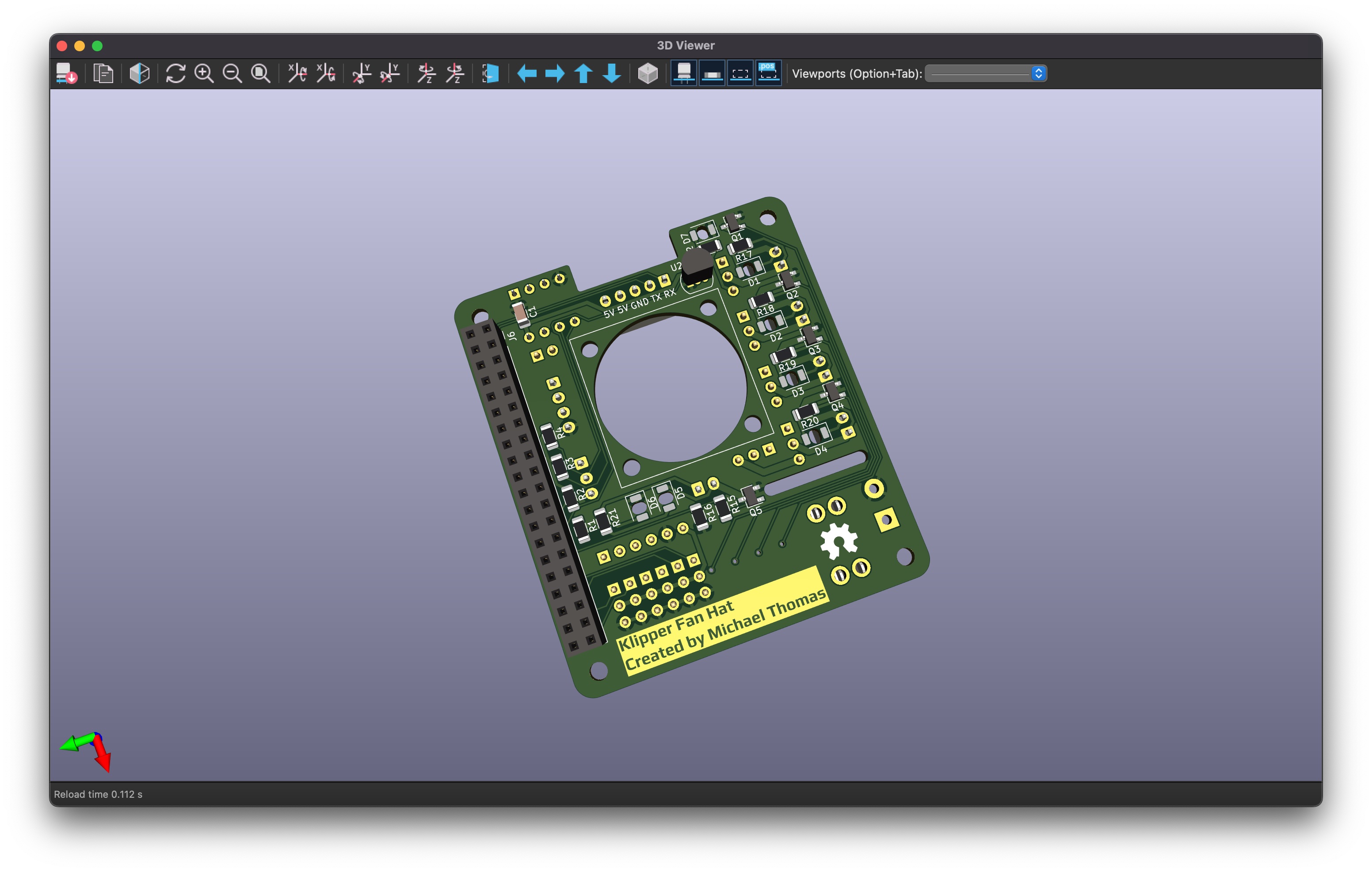
Two versions of the board have been produced:
I used PCBWay to produce the PCBs.
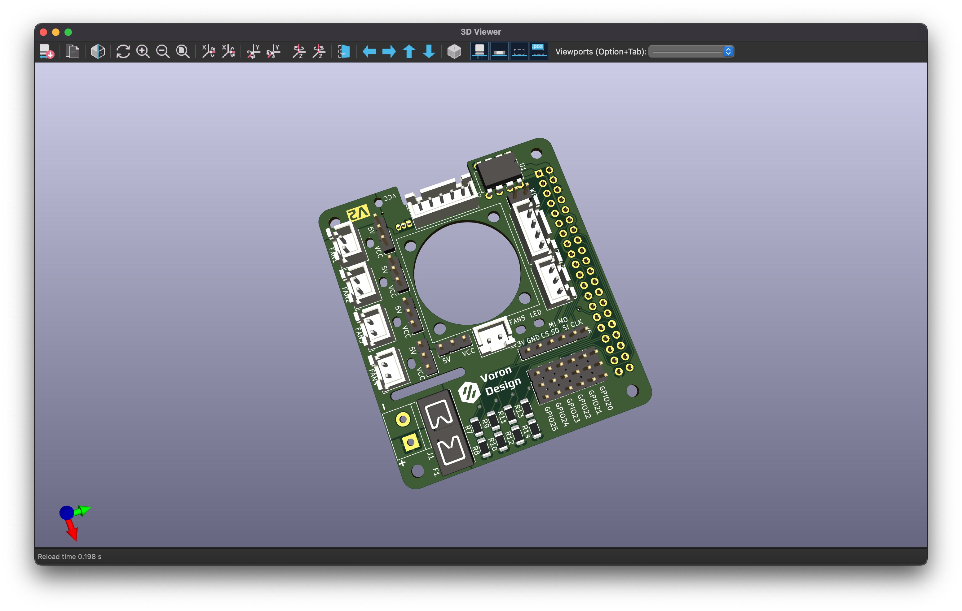
Although currently untested, the main branch contains the updated version of the board, V2, with a few revisions to fix some bugs that were found when testing the first version of the board.
Parts Required
The reference numbers in the notes field refer to the parts required marked on the silkscreen and can be seen in the interactive BOM.
Fasteners
| Item | Quantity | Received | Notes |
|---|---|---|---|
| M2.5x6 BHCS | 4 | 50 | To mount the hat to the Raspberry Pi |
| M2.5x14 BHCS | 4 | 10 | To mount the Fan |
| M2.5 Nut | 4 | 50 | To mount the Fan |
| M2.5 Brass Standoff | 4 | 16 | To stop the fan inputs shorting on the HDMI Socket |
Connectors
| Item | Quantity | Received | Notes |
|---|---|---|---|
| 2 Pin JST-XH Header | 5 | 20 | FAN1-FAN5 |
| 3 Pin JST-XH Header | 1 | 20 | J4 |
| 4 Pin JST-XH Header | 1 | 20 | J3 |
| 5 Pin JST-XH Header | 1 | 20 | J2 |
| 40 Pin Raspberry Pi Header | 1 | 7 | J8 |
| Dupont Pin Headers | 41 Pins | 10 x 40 pin strips | J7, JP1-JP5, WP1, GPIO20-GPIO25 |
| Jumper Cap 2.54mm | 6 | 109 | JP1-JP5, WP1 |
| KF301 Screw Terminal (5mm pitch) | 1 | 10 | J1 |
| PCB Panel Mount Blade Fuse Holder | 1 | 10 | F1 |
SMD Components
| Item | Quantity | Received | Notes |
|---|---|---|---|
| 100nF Capacitor (1206 Package) | 1 | 20 | C1 |
| 100Ω Resistor (1206 Package) | 5 | 123 | R7, R9, R11, R13, R15 |
| 1kΩ Resistor (1206 Package) | 1 | 127 | R1 |
| 3.9kΩ Resistor (1206 Package) | 2 | 112 | R2-R3 |
| 4.7kΩ Resistor (1206 Package) | 7 | 103 | R4, R17-R22 |
| 10kΩ Resistor (1206 Package) | 5 | 111 | R8, R10, R12, R14, R16 |
| LED Red (1206 Package) | 7 | 105 | D1-D7 |
| IRLML6344-TRPBF Mosfet (SOT-23 Package) | 5 | 100 | Q1-Q5 |
Misc
| Item | Quantity | Received | Notes |
|---|---|---|---|
| 2510 Axial Fan | 1 | 2 | |
| CAT24C32 EEPROM | 1 | 15 | U1 |
| DIP-8 Socket | 1 | 20 | Not required, but makes switching EEPROM modules out easier for testing |
| DS18B20 Temperature Sensor | 1 | 15 |
Note
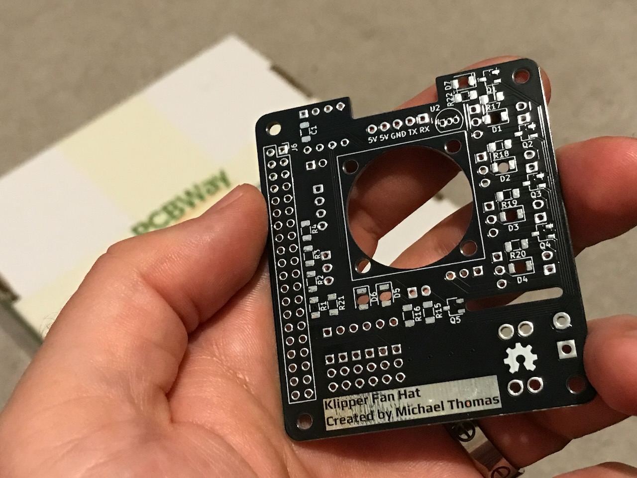
Some of the images on this page show Version 1 of the PCB, It was originally called the Klipper Expander Hat however I have subsequently renamed it to Klipper Fan Hat as decided on the Voron Discord this was so that should not be confused with the Klipper Expander.
Assembly and Testing
At present assembly testing has only been done with Version 1 of the Klipper Fan hat.
Assembly
Excuse the messy soldering, this is the first time I have tried to solder Surface Mount Device (SMD) components, and the pads are TINY, I'm probably going to need to invest in a TS100 (...and provides an excuse to buy a shiny new toy).

The first time powering the Hat up, I connected the Mosfets to 5V from the Raspberry Pi USB input. All 5 Fan output LEDs lit up which made me happy, however, this happiness was short lived, as I unfortunately found a major design flaw in my design...
Testing
I used one of my abused Raspberry Pis that I did not mind if I destroyed by releasing its "Magic Smoke" whilst testing the board. This is a Raspberry Pi 3 that unfortunately has lost its ability to talk to Wifi or Bluetooth devices, hence the USB wifi module you can see in any pictures.
I have connected a 12V power supply to VCC for testing, however it should also work for 24V. I switched the power selector jumpers for the Fan mosfets to VCC and tried to switch 12V Fans which also worked succesfully. I have also connected a mini OLED display to the I2C bus and managed to get it to output the default Klipper display.
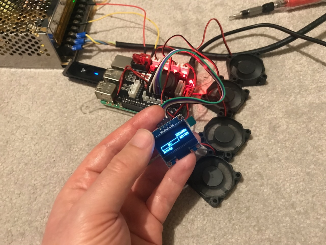
I have yet to test the Serial port; it just passes the connections directly to the GPIO pins the same way as the I2C port does, so I am pretty sure it will work.
Now to the major design flaw - I neglected to check if the Raspberry Pi is capable of analog input (spoiler - it's not) I have looked into adding an Analog to Digital Converter (ADC), however it will take up quite a bit of space on the board and I am unsure if I could get it to work with Klipper. I have therefore opted to remove the thermistor ports in favour of 2 General Purpose Input/Output connectors for connecting items such as Filament Runout Sensors instead.
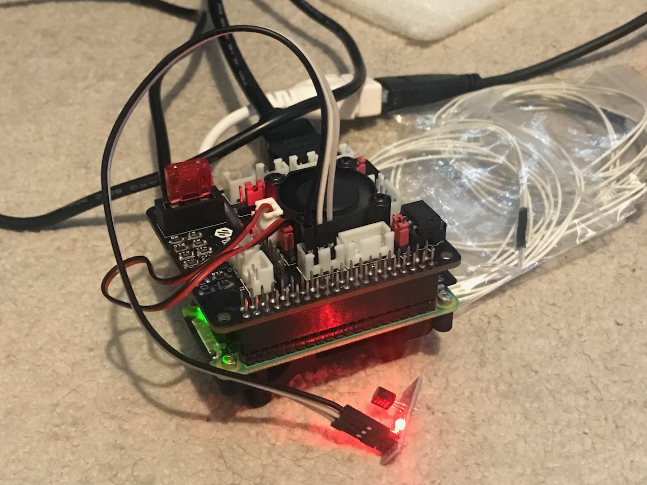
If a temperature sensor is required, I have tested a couple of different DS18B20 temperature sensors, they connect to the 1-wire port and are be compatable with Klipper. It is also possible to connect a HTU21D Temperature and Humidity sensor to the I2C port that is also compatible with Klipper.
I also have a DHT11 temperature sensor to test on the 1-Wire port. This is not currently compatible with Klipper, but could be used with a Python script running directly on the Pi.
After further testing, I have noticed I have used some incorrect resistor values in some places, I have now updated these to the correct values. I have also removed the decoupling capacitors from the thermistor ports and changed the pull up resistors to 3.9kΩ so that I can repurpose the non working thermistor ports as GPIO the same way I have added into V2.
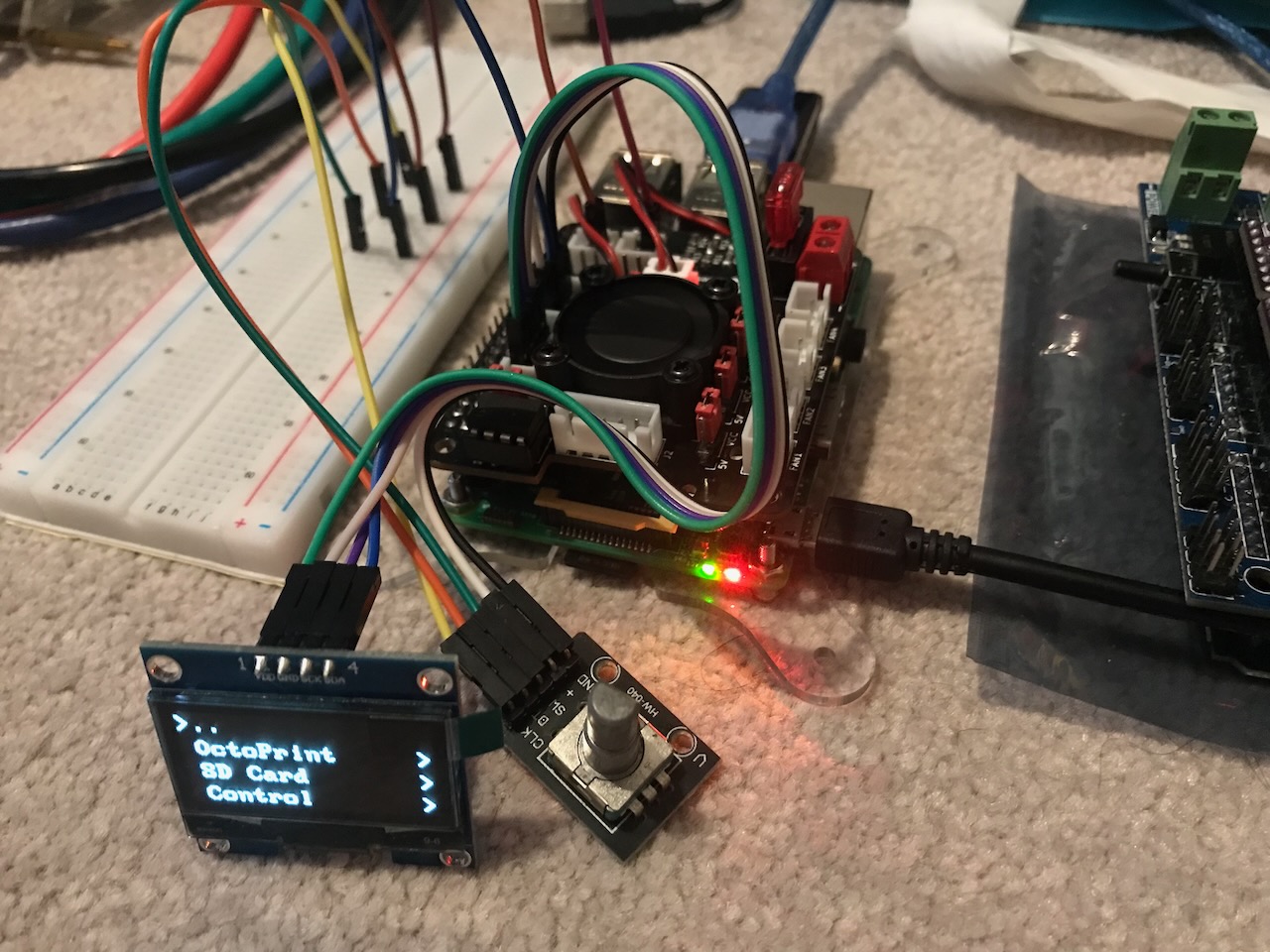
These have been tested by connecting the 1-wire and the two GPIO pins to a rotary encoder, and I have also tested a microswitch acting as a filament runout sensor. Both of which worked perfectly and I have added example configuration sections to the Klipper config file.
The Road to V2

After my testing I identified a few improvements that I have now made and are available in the master branch:
- Rename to Klipper Fan Hat
- Increase the thickness of the power delivery tracks
- Increase the thickness of the mosfet tracks
- Covered entire bottom side with ground plane
- Move the EEPROM decoupling capacitor closer to the chip
- Add pull up resistor to the 1-Wire pin
- Move Fan 5 power selector header to the other side of the connector to allow space for fan wiring
- Add missing component markings for power LED, it's resistor and power input screw terminal
- Add pin markings to the silkscreen for Power, Serial, SPI and I2C
- Replace non-working thermistor inputs with GPIO connectors
- Switch orientation of Fan 1-4 resistors so that it does't matter if they are bridged when soldering
- Added a status LED that can be controlled by the Klipper host
- On Board DS18B20 Temperature Sensor
I have received the printed circuit boards for Version 2 of the fan hat however I have not yet assembled one. I have however, purchased a cheap Hot Air Soldering station to hopefully put some together a little more professionally with the aim to eventually sell on the pcb_party channel on the Voron Discord so watch this space if you would like to puchase one.
Flash Hat EEPROM
Install git
We will need to install Git so we can check out the Raspberry Pi Hats Repository as it is not included in the base Raspberry Pi OS image.
pi@raspberrypi:~ $ sudo apt update
...
pi@raspberrypi:~ $ sudo apt install git
Reading package lists... Done
Building dependency tree... Done
Reading state information... Done
The following additional packages will be installed:
  git-man liberror-perl
Suggested packages:
  git-daemon-run | git-daemon-sysvinit git-doc git-el git-email git-gui gitk gitweb git-cvs git-mediawiki git-svn
The following NEW packages will be installed:
  git git-man liberror-perl
0 upgraded, 3 newly installed, 0 to remove and 13 not upgraded.
Need to get 6,533 kB/6,564 kB of archives.
After this operation, 33.1 MB of additional disk space will be used.
Do you want to continue? [Y/n] y
...
Setting up git (1:2.30.2-1+deb11u2) ...
Clone Hats Git Repository
Next we need to get the code from the Raspberry Pi Hats Repository.
pi@raspberrypi:~ $ git clone https://github.com/raspberrypi/hats.git
Cloning into 'hats'...
remote: Enumerating objects: 624, done.
remote: Counting objects: 100% (154/154), done.
remote: Compressing objects: 100% (65/65), done.
remote: Total 624 (delta 100), reused 131 (delta 89), pack-reused 470
Receiving objects: 100% (624/624), 326.80 KiB | 1.56 MiB/s, done.
Resolving deltas: 100% (366/366), done.
Make EEPROM Utils
Once we have cloned the repository we need to compile the tools to make the EEPROM image and flash it to the chip.
pi@raspberrypi:~ $ cd hats/eepromutils/
pi@raspberrypi:~/hats/eepromutils $ make -j4
cc -Wall -Wextra eepmake.c -o eepmake
cc -Wall -Wextra eepdump.c -o eepdump
pi@raspberrypi:~/hats/eepromutils $ ls
eepdump  eepdump.c  eepflash.sh  eepmake  eepmake.c  eeprom_settings.txt  eeptypes.h  Makefile  README.md
Enable I2C
To communicate with the EEPROM chip we need to enable the I2C interface.
pi@raspberrypi:~/hats/eepromutils $ sudo raspi-config
Select: interfacing Options -> I2C -> Yes -> ok -> Finish
We will then need to reboot the Raspberry Pi to enable.
pi@raspberrypi:~/hats/eepromutils $ sudo reboot
When finished restarting, we will need to install the i2c-tools package, log in and run:
pi@raspberrypi:~ $ sudo apt install i2c-tools
Reading package lists... Done
Building dependency tree... Done
Reading state information... Done
The following additional packages will be installed:
  libi2c0 read-edid
Suggested packages:
  libi2c-dev python-smbus
The following NEW packages will be installed:
  i2c-tools libi2c0 read-edid
0 upgraded, 3 newly installed, 0 to remove and 13 not upgraded.
Need to get 103 kB of archives.
After this operation, 359 kB of additional disk space will be used.
Do you want to continue? [Y/n] y
...
Setting up i2c-tools (4.2-1+b1) ...
Connect EEPROM
The Raspberry Pi should be powered off before making any connections to the GPIO pins.
pi@raspberrypi:~ $ sudo halt
We will then need to connect the EEPROM chip as per the following diagram, I did not add the RGB LED or its resistors as I just wanted to flash the EEPROM.

Image © 2016 The MagPi Magazine
I did not have any 3.9kΩ resistors available but I used 4.7kΩ without any problems.
Switch the Raspberry Pi back on.
Test EEPROM is Connected
If when we try to detect the EEPROM we get a 'No such file or directory' error such as...
pi@raspberrypi:~ $ i2cdetect -y 9
Error: Could not open file `/dev/i2c-9' or `/dev/i2c/9': No such file or directory
...run the following command as explained in the EEPROM Utils Docs.
pi@raspberrypi:~ $ sudo dtoverlay i2c-gpio i2c_gpio_sda=0 i2c_gpio_scl=1 bus=9
You should then be able to see the EEPROM Chip at address 50:
pi@raspberrypi:~ $ i2cdetect -y 9
     0  1  2  3  4  5  6  7  8  9  a  b  c  d  e  f
00:                         -- -- -- -- -- -- -- --
10: -- -- -- -- -- -- -- -- -- -- -- -- -- -- -- --
20: -- -- -- -- -- -- -- -- -- -- -- -- -- -- -- --
30: -- -- -- -- -- -- -- -- -- -- -- -- -- -- -- --
40: -- -- -- -- -- -- -- -- -- -- -- -- -- -- -- --
50: 50 -- -- -- -- -- -- -- -- -- -- -- -- -- -- --
60: -- -- -- -- -- -- -- -- -- -- -- -- -- -- -- --
70: -- -- -- -- -- -- -- --
Zero EEPROM
The Recommended EEPROM in the Design Guide at the time of writing is CAT24C32 which is 32kbit (4kbyte).
As we don't know the state of the EEPROM it is best to clear it by setting it all to zeros. If your EEPROM is a different size you will need to set count to the value of kbyte of your chip.
Make a blank image using dd:
pi@raspberrypi:~ $ cd hats/eepromutils/
pi@raspberrypi:~/hats/eepromutils $ dd if=/dev/zero ibs=1k count=4 of=blank.eep
4+0 records in
8+0 records out
4096 bytes (4.1 kB, 4.0 KiB) copied, 0.000941149 s, 4.4 MB/s
Verify it is actually blank with hexdump...
pi@raspberrypi:~/hats/eepromutils $ hexdump blank.eep
0000000 0000 0000 0000 0000 0000 0000 0000 0000
*
0001000
...and flash it to the chip.
pi@raspberrypi:~/hats/eepromutils $ sudo ./eepflash.sh -w -f=blank.eep -t=24c32
This will attempt to talk to an eeprom at i2c address 0x50. Make sure there is an eeprom at this address.
This script comes with ABSOLUTELY no warranty. Continue only if you know what you are doing.
Do you wish to continue? (yes/no): yes
Writing...
4096 bytes (4.1 kB, 4.0 KiB) copied, 17 s, 0.2 kB/s
8+0 records in
8+0 records out
4096 bytes (4.1 kB, 4.0 KiB) copied, 16.7208 s, 0.2 kB/s
Closing EEPROM Device.
Done.
Flash EEPROM
Now that we have a blank EEPROM chip, we can configure and flash the Hat EEPROM image to it. Open the eeprom_settings.txt file:
pi@raspberrypi:~/hats/eepromutils $ nano eeprom_settings.txt
Update the contents with the Klipper Fan Hat settings file from the Repository.
Save and close the file, and then we can make the EEPROM image...
pi@raspberrypi:~/hats/eepromutils $ ./eepmake eeprom_settings.txt klipper-fan-hat.eep
Opening file eeprom_settings.txt for read
UUID=fef562f0-9e28-4453-88c2-c073303e6ab2
Done reading
Writing out...
Done.
...and flash it to the chip.
pi@raspberrypi:~/hats/eepromutils $ sudo ./eepflash.sh -w -f=klipper-fan-hat.eep -t=24c32
This will attempt to talk to an eeprom at i2c address 0x50. Make sure there is an eeprom at this address.
This script comes with ABSOLUTELY no warranty. Continue only if you know what you are doing.
Do you wish to continue? (yes/no): yes
Writing...
0+1 records in
0+1 records out
215 bytes copied, 0.788403 s, 0.3 kB/s
Closing EEPROM Device.
Done.
Test EEPROM
The Hat EEPROM is read on system boot so we will need to reboot the Pi before we can test it:
pi@raspberrypi:~/hats/eepromutils $ sudo reboot
We can then read the data using the device tree:
pi@raspberrypi:~ $ cd /proc/device-tree/hat/
pi@raspberrypi:/proc/device-tree/hat $ ls
custom_0  name  product  product_id  product_ver  uuid  vendor
pi@raspberrypi:/proc/device-tree/hat $ more name
hat
pi@raspberrypi:/proc/device-tree/hat $ more vendor
Voron Design
pi@raspberrypi:/proc/device-tree/hat $ more product
Klipper Fan Hat
pi@raspberrypi:/proc/device-tree/hat $ more product_id
0x4b46
pi@raspberrypi:/proc/device-tree/hat $ more product_ver
0x0002
pi@raspberrypi:/proc/device-tree/hat $ more uuid
fef562f0-9e28-4453-88c2-c073303e6ab2
Enable I2C and SPI Automatically
To allow the hat to automatically enable I2C and SPI we will create a device tree overlay and embed it into the EEPROM. The Raspberry Pi will then enable this at boot time.
pi@raspberrypi:~/hats/eepromutils $ nano klipper-fan-hat.dts
Update the contents with the Klipper Fan Hat device tree source file from the Repository.
Save the file, compile the binary and set the correct permissions to the output file:
pi@raspberrypi:~/hats/eepromutils $ sudo dtc -@ -I dts -O dtb -o klipper-fan-hat.dtb klipper-fan-hat.dts
pi@raspberrypi:~/hats/eepromutils $ sudo chown pi:pi klipper-fan-hat.dtb
You may need to install the device-tree-compiler package if you get any errors running the previous command, however, it was already installed in the version of Raspberry Pi OS that I was using.
pi@raspberrypi:~/hats/eepromutils $ sudo apt-get install device-tree-compiler
We can then embed the device tree binary into the flash file...
pi@raspberrypi:~/hats/eepromutils $ ./eepmake eeprom_settings.txt klipper-fan-hat-with-dt.eep klipper-fan-hat.dtb
Opening file eeprom_settings.txt for read
UUID=967cd2a4-9c61-4397-ae2e-5184a7f2b7de
Done reading
Opening DT file klipper-fan-hat.dtb for read
Adding 411 bytes of DT data
Writing out...
Writing out DT...
Done.
...and flash it to the EEPROM the same way we did before:
pi@raspberrypi:~/hats/eepromutils $ sudo ./eepflash.sh -w -f=blank.eep -t=24c32
This will attempt to talk to an eeprom at i2c address 0x50. Make sure there is an eeprom at this address.
This script comes with ABSOLUTELY no warranty. Continue only if you know what you are doing.
Do you wish to continue? (yes/no): yes
Writing...
4096 bytes (4.1 kB, 4.0 KiB) copied, 17 s, 0.2 kB/s
8+0 records in
8+0 records out
4096 bytes (4.1 kB, 4.0 KiB) copied, 16.6287 s, 0.2 kB/s
Closing EEPROM Device.
Done.
pi@raspberrypi:~/hats/eepromutils $ sudo ./eepflash.sh -w -f=klipper-fan-hat-with-dt.eep -t=24c32
This will attempt to talk to an eeprom at i2c address 0x50. Make sure there is an eeprom at this address.
This script comes with ABSOLUTELY no warranty. Continue only if you know what you are doing.
Do you wish to continue? (yes/no): yes
Writing...
512 bytes copied, 2 s, 0.3 kB/s
1+1 records in
1+1 records out
636 bytes copied, 2.40116 s, 0.3 kB/s
Closing EEPROM Device.
Done.
We can check that I2C and SPI is enabled by switching off I2C using raspi-config the same way we enabled it except clicking No when prompted to enable.
After another restart you will be able to see the devices /dev/i2c-1, and /dev/spidev0.0 and /dev/spidev0.1 only when the hat EEPROM is connected.
pi@raspberrypi:~ $ ls /dev
autofs         dma_heap   i2c-1    loop4         mmcblk0    ram1   ram5     spidev0.0  tty12  tty21  tty30  tty4   tty49  tty58  ttyAMA0    vcs1   vcsa4     vcsu6    video20
block          dri        i2c-2    loop5         mmcblk0p1  ram10  ram6     spidev0.1  tty13  tty22  tty31  tty40  tty5   tty59  ttyprintk  vcs2   vcsa5     vhci     video21
btrfs-control  fd         initctl  loop6         mmcblk0p2  ram11  ram7     stderr     tty14  tty23  tty32  tty41  tty50  tty6   uhid       vcs3   vcsa6     video10  video22
bus            full       input    loop7         mqueue     ram12  ram8     stdin      tty15  tty24  tty33  tty42  tty51  tty60  uinput     vcs4   vcsm-cma  video11  video23
cachefiles     fuse       kmsg     loop-control  net        ram13  ram9     stdout     tty16  tty25  tty34  tty43  tty52  tty61  urandom    vcs5   vcsu      video12  video31
cec0           gpiochip0  log      mapper        null       ram14  random   tty        tty17  tty26  tty35  tty44  tty53  tty62  v4l        vcs6   vcsu1     video13  watchdog
char           gpiochip1  loop0    media0        ppp        ram15  rfkill   tty0       tty18  tty27  tty36  tty45  tty54  tty63  vchiq      vcsa   vcsu2     video14  watchdog0
console        gpiochip2  loop1    media1        ptmx       ram2   serial1  tty1       tty19  tty28  tty37  tty46  tty55  tty7   vcio       vcsa1  vcsu3     video15  zero
cuse           gpiomem    loop2    media2        pts        ram3   shm      tty10      tty2   tty29  tty38  tty47  tty56  tty8   vc-mem     vcsa2  vcsu4     video16
disk           hwrng      loop3    mem           ram0       ram4   snd      tty11      tty20  tty3   tty39  tty48  tty57  tty9   vcs        vcsa3  vcsu5     video18
Embed Klipper config in EEPROM
pi@raspberrypi:~/hats/eepromutils $ nano klipper-fan-hat.cfg
Update the contents with the Klipper config source file from the Repository.
Save the file, and embed the config file into the EEPROM image
pi@raspberrypi:~/hats/eepromutils $ ./eepmake eeprom_settings.txt klipper-fan-hat-with-dt.eep klipper-fan-hat.dtb -c klipper-fan-hat.cfg
Opening file eeprom_settings.txt for read
UUID=62ed7b88-3e38-4958-a397-5271702f3386
Done reading
Opening DT file klipper-fan-hat.dtb for read
Adding 411 bytes of DT data
Opening custom data file klipper-fan-hat.cfg for read
Adding 3450 bytes of custom data
Writing out...
Writing out DT...
Done.
...then flash the EEPROM
pi@raspberrypi:~/hats/eepromutils $ sudo ./eepflash.sh -w -f=blank.eep -t=24c32
This will attempt to talk to an eeprom at i2c address 0x50. Make sure there is an eeprom at this address.
This script comes with ABSOLUTELY no warranty. Continue only if you know what you are doing.
Do you wish to continue? (yes/no): yes
Writing...
4096 bytes (4.1 kB, 4.0 KiB) copied, 17 s, 0.2 kB/s
8+0 records in
8+0 records out
4096 bytes (4.1 kB, 4.0 KiB) copied, 16.5953 s, 0.2 kB/s
Closing EEPROM Device.
Done.
pi@raspberrypi:~/hats/eepromutils $ sudo ./eepflash.sh -w -f=klipper-fan-hat-with-dt.eep -t=24c32
This will attempt to talk to an eeprom at i2c address 0x50. Make sure there is an eeprom at this address.
This script comes with ABSOLUTELY no warranty. Continue only if you know what you are doing.
Do you wish to continue? (yes/no): yes
Writing...
4096 bytes (4.1 kB, 4.0 KiB) copied, 19 s, 0.2 kB/s
8+0 records in
8+0 records out
4096 bytes (4.1 kB, 4.0 KiB) copied, 19.0053 s, 0.2 kB/s
Closing EEPROM Device.
Done.
Restart the Pi and we can then copy the config out of the device tree into the klipper config directory.

Klipper Setup
To set up Klipper on a Raspberry Pi using the same Pi as secondary mcu, you can follow the steps in the RPi microcontroller section of my Klipper Firmware setup page.
Remaining configuration
Once you have the RPi microcontroller set up, you can copy the config from the EEPROM chip of the hat into the Klipper config directory, using the following command:
cat /proc/device-tree/hat/custom_1 > ~/printer_data/config/klipper-fan-hat.cfg